![]()
Telecentric optical system is an optical design that where the principal ray in parallel to the optical axis. It eliminates distortion problems by collimating the light entering the lens and suitable for imaging 3D objects. Co-axial illumination is suitable for recognizing object with high reflectance such as wafer, glass, and metal.
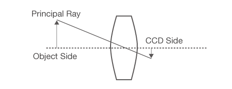
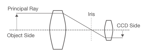
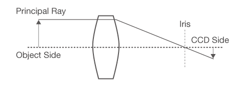
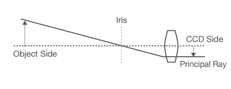


Size of 3D object changes when it goes up and down when non-telecentric lens is used.
Telecentric lens is suitable for accurate measurement of 3D object.
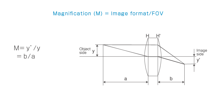
Most of lenses in this catalogue are designed for finite distance. Image format (sensor size) divided by object size equal to optical magnification. It is the most important to select a lens.
| Image Size(inch) | 1/3 | 1/2.5 | 1/2 | 1/1.8 |
2/3 (5MP) |
1(5MP) | 1(20MP) | 1.1(12MP) | 1.1(25MP) | 4/3 |
|---|---|---|---|---|---|---|---|---|---|---|
| Vertical(mm) | 3.6 | 4.27 | 4.8 | 5.35 | 7.1 | 10.2 | 8.81 | 10.35 | 12.8 | 13 |
| Horizonal(mm) | 4.8 | 5.7 | 6.4 | 7.14 | 8.47 | 12.8 | 13.19 | 14.13 | 12.8 | 17.3 |
| Diagonal(mm) | 6 | 7.12 | 8 | 8.93 | 11 | 16.4 | 15.86 | 17.5 | 18.1 | 23.5 |
| Resolution(Mega Pixel) | 19.6MP | 20MP | 25MP | 31MP | 51MP | 61MP | 65MP | 71MP | 101MP | 120MP | 151MP |
|---|---|---|---|---|---|---|---|---|---|---|---|
| Resolution(H x V) | 4416 x 4428 | 5120 x 3840 | 5120 x 5120 | 6464 x 4852 | 8424 x 6032 | 9588 x 6380 | 9344 x 7000 | 10000 x 7096 | 11648 x 8742 | 13264 x 9176 | 14192 x 10640 |
| Pixel size(μm) | 3.45 | 6.4 | 4.5 | 3.45 | 4.6 | 3.76 | 3.2 | 3.1 | 3.76 | 2.2 | 3.76 |
| Vertical(mm) | 15.24 | 24.6 | 23.04 | 22.3 | 38.75 | 35.98 | 29.9 | 31 | 43.8 | 29.18 | 53.36 |
| Horizonal(mm) | 15.28 | 32.8 | 23.04 | 16.74 | 27.75 | 23.99 | 22.4 | 22 | 32.87 | 20.19 | 40.01 |
| Diagonal(mm) | 21.6 | 41 | 32.6 | 27.9 | 47.7 | 43.2 | 37.4 | 38 | 54.8 | 35.5 | 66.7 |
Examples of area sensor and large area sensor . Different size of sensor will be expected to be available for v arious applications.
| Sensor Size(mm) | 10.24 | 14.34 | 20.48 | 28.67 | 28.67 | 35 | 36 | 57.34 | 57.34 | 61.44 | 81.92 |
|---|---|---|---|---|---|---|---|---|---|---|---|
| Pixel size(μm) | 10 | 14 | 10 | 14 | 7 | 4.7 | 7 | 7 | 3.5 | 5 | 5 |
| Resolution(pixel) | 1024 | 1024 | 2048 | 2048 | 4096 | 7450 | 5150 | 8192 | 16384 | 12288 | 16384 |
Length of line sensor is formed, depended on pixel size and resolution. As the sensor size is larger, design and
manufacture of a lens for line sensor are more difficult and complicated.
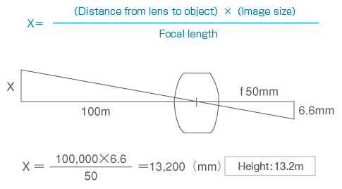
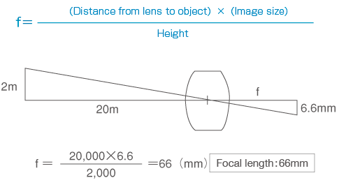
The actual size of a viewed object that can be taken when a len s is mounted to a camera.
Ex). Magnification: 0.5x Image format: 1/2

Magnification of an image on a CCD camera when it is displayed on a monitor screen.
Magnification of an object displayed on a monitor screen through a lens.
Ex). Magnification: 0.5x Image format: 1/2 Monitor size: 15 inch (1 inch = 25.4mm)

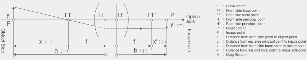
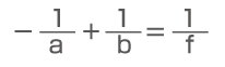
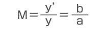
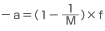
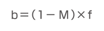
| Basics formula | Horizontal magnification | Object point distance | Image point distance |
|---|---|---|---|
 |
 |
 |
 |
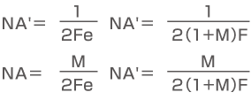
| Relationship of object side NA and image side NA (NA’) |
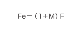
Relationship of F No. and Effective F no.(Fe) | Relationship of NA and Effective F No. |
|---|---|---|
 |
 |
 |
